
[vc_row][vc_column css_animation=”none”][vc_row_inner][vc_column_inner css=”.vc_custom_1712144297575{padding-top: 89px !important;padding-bottom: 10px !important;}”][vc_column_text]
ALUCOBOND® PLUS
[/vc_column_text][/vc_column_inner][/vc_row_inner][vc_row_inner][vc_column_inner width=”2/3″][vc_column_text]Whether your project is a private home, a corporate space, a large public building, or an industrial complex – ALUCOBOND® PLUS lets you take creativity to the next level.[/vc_column_text][/vc_column_inner][vc_column_inner width=”1/3″][vc_single_image image=”5596″ img_size=”full”][/vc_column_inner][/vc_row_inner][edgtf_accordion content_width=”full-width” skin=”light” custom_class=”product-accordion”][edgtf_accordion_tab title_tag=”h4″ title=”Product Properties”][vc_row_inner][vc_column_inner width=”1/2″][vc_column_text]ALUCOBOND® PLUS is a composite panel consisting of two aluminium cover sheets with a hardly flammable mineral-filled core and has been developed exclusively for the stringent fire regulations in architecture.
This next generation product boasts a range of fantastic properties such as surface flatness, formability, resistance to weather and simple processing. With myriad applications ALUCOBOND® PLUS is used extensively for airports, metro stations, railway stations, stadiums, corporate parks, IT parks, high rise towers, malls, etc.[/vc_column_text][/vc_column_inner][vc_column_inner width=”1/2″][vc_single_image image=”5602″ img_size=”full”][/vc_column_inner][/vc_row_inner][vc_column_text css=”.vc_custom_1704268578920{padding-bottom: 2em !important;}”]
| CHARACTERISTICS |
ADVANTAGES |
|---|---|
| Low weight, high rigidity, perfect flatness | Low cost for substructures and fasteners, Smooth handling on the site |
| Large variety of colours | Unlimited planning and design |
| Weatherproof | Supplied ready to install |
| Vibration-damping | No additional sound-damping needed |
| Can easily be folded and bent | Simple processing using conventional tools |
| Large panel sizes, fast installation, pre-fabricated panels | Short construction times, adherence to schedules, low cost |
Due to its composite structure, ALUCOBOND® PLUS can take on many different shapes – think of it like a separate ‘skin’ that wraps around a building’s structure, adapting and flowing with its contours. However, this material’s perfect formability does not affect its stability and flatness – the high rigidity of the panel remains.[/vc_column_text][edgtf_image_gallery type=”grid” enable_image_shadow=”no” number_of_columns=”three” space_between_items=”normal” images=”5609,5607,5608″ image_size=”full”][vc_column_text]
Lightness meets rigidity
The composite structure of ALUCOBOND® PLUS means it has an impressive strength to weight ratio, no matter if it is a large sized panel. Despite its low weight – which makes ALUCOBOND® PLUS easy to transport and handle – its rigidity helps maintain its shape and flatness, even when exposed to extreme temperature changes.
Comparison of thickness and weight of panels with equal rigidity

| ALUCOBOND® PLUS | Aluminium | ||||
| Rigidity (E·J) | Section modulus | Thickness | Weight | Thickness | Weight |
| 1250 kN cm²/m | 1.25 cm³/m | 3 mm | 5.9 kg/m² | 2.7 mm | 7.3 kg/m² |
| 2400 kN cm²/m | 1.75 cm³/m | 4 mm | 7.6 kg/m² | 3.3 mm | 8.9 kg/m² |
Sustainability
3A Composites: Environment, Safety, and Quality
3A Composites is the parent company of ALUCOBOND and is recognized across the globe as one of the leaders in the field of sustainability. Its reputation is spread far and wide, including among other diversified producers and raw material processing companies around the world.
The company’s unflinching commitment to sustainability – along with taking the needs of all key groups into account – enables it to make decisions of the highest economic, social, and ecological value. 3A Composites also commits to continuous self-improvement programs for environmental protection, many of which exceed government regulations.
ALUCOBOND Lifecycle
Over decades of use in a rear-ventilated cladding system, ALUCOBOND® PLUS protects a building from weathering and the harmful effects of industrial and environmental pollution. It also acts as a barrier against solar radiation; the ventilated space between the ALUCOBOND® PLUS panels and the wall or the thermal insulation reduces heat transmission.
[/vc_column_text][vc_row_inner content_placement=”middle” css=”.vc_custom_1704268807292{padding-top: 2em !important;padding-bottom: 2em !important;}”][vc_column_inner width=”1/4″][vc_single_image image=”5619″ img_size=”173×410″][/vc_column_inner][vc_column_inner width=”3/4″][vc_column_text]
The major advantages
- Lower maintenance costs
- Long-term preservation of the building’s structure
- During winter there are major savings in heating costs
- In summer there are major savings in air-conditioning costs
- Reduction of thermal expansion
- Reduction in crack formation
[/vc_column_text][/vc_column_inner][/vc_row_inner][vc_column_text]
Recycling
ALUCOBOND® PLUS is fully recyclable. Both the core material and the aluminium cover sheets can be used in the production of new material.[/vc_column_text][/edgtf_accordion_tab][edgtf_accordion_tab title=”Product Range”][vc_column_text]
| ALUCOBOND® PLUS | Thickness: 3/4mm |
|---|
| Width (mm) | 1000 | 1250 | 1500 | 1575 | 1750 |
|---|---|---|---|---|---|
| Length (mm) | 2500-6999 | 2500-6999 | 2500-6999 | 2500-6999 | 2500-6999 |
| Solid Colours |  |
|
|
|
 |
| Metallic Colours | |
|
|
|
|
| Spectra & Sparkling | |
|
|
|
|
| ALUCOBOND® Anodized Look | |
|
|
|
|
| ALUCOBOND® natural | |
|
|||
| ALUCOBOND® Legno | |
|
|
||
| ALUCOBOND® Vintage | |
|
|
||
| ALUCOBOND® Façade design | |
|
|
||
| ALUCOBOND® Urban | |
|
|
||
| ALUCOBOND® Wood | |
|
|||
| ALUCOBOND® Terra | |
|
|||
| ALUCOBOND® Rocca | |
|
|||
| ALUCOBOND® Anodized * | |
|
|||
| Custom Colours | |
|
|
|
|
| ALUCOBOND® design | |
|
|
||
Footnotes:
on request
Dimensional Tolerances
[/vc_column_text][vc_row_inner][vc_column_inner width=”1/2″][vc_column_text]Due to manufacturing, a displacement of the cover sheets sidewise at the panel edges up to 2 mm is possible.
Thickness: ± 0,2 mm
(mill-finish | stove lacquered | anodized)
Width: – 0 / + 4 mm
Lengths: 2500 – 400 mm; – 0 / + 6
Lengths: 4001– 6999 mm; – 0 / + 10 mm[/vc_column_text][/vc_column_inner][vc_column_inner width=”1/2″][vc_column_text]* Anodized according to DIN 17611. All anodized ALUCOBOND® composite panels have contact lines (about 25 mm width) on their short sides. For panel lengths of more than 3500 mm, the composite panels have contact lines (about 2 – 3 mm width) on their long sides. Maximum panel length 6999 mm. Please take this into consideration when dimensioning the panels.[/vc_column_text][/vc_column_inner][/vc_row_inner][/edgtf_accordion_tab][edgtf_accordion_tab title=”Technical Data”][vc_column_text]
| THICKNESS | STANDARDS | UNIT | 3MM | 4MM | |
|---|---|---|---|---|---|
| Thickness of Aluminium Layers |
[mm] | 0.5 | |||
| Weight | [kg/m²] | 5.9 | 7.6 | ||
| Width | [mm] | 1000 / 1250 / 1500 (1575 / 1750) | |||
| TECHNICAL PROPERTIES | |||||
| Section modulus | W | DIN 53293 | [cm³/m] | 1.25 | 1.75 |
| Rigidity | E·J | DIN 53293 | [kNcm²/m] | 1250 | 2400 |
| Alloy / Temper of Aluminium Layers |
EN 573-3 EN 515 |
EN AW 5005A (AIMg1) H22 / H42 |
|||
| Modulus of Elasticity | EN 1999 1-1 | [N/mm²] | 70.000 | ||
| Tensile Strength of Aluminium | EN 485-2 | [N/mm²] | Rm ≥ 130 | ||
| 0.2 % Proof Stress | EN 485-2 | [N/mm²] | Rp0,2 ≥ 90 | ||
| Elongation | EN 485-2 | [%] | A50 ≥ 5 | ||
| Linear Thermal Expansion |
EN 1999 1-1 | 2.4 mm/m at 100ºC temperature difference | |||
| CORE | |||||
| Mineral filled polymer | |||||
| SURFACE | |||||
| Lacquering | Coil Coating Fluorocarbon (e.g. PVDF) |
||||
| Gloss (initial value) | EN 13523-2 | [%] | 30-80 | ||
| Pencil Hardness | EN 13523-4 | HB-F | |||
| ACOUSTICAL PROPERTIES | |||||
| Sound Absorption Factor | αs | ISO 354 | 0.05 | ||
| Sound Transmission Loss | Rw | ISO 717-1 | [dB] | ≥ 25 | |
| THERMAL PROPERTIES | |||||
| Thermal Resistance | R | DIN 52612 | [m²K/W] | 0.007 | 0.009 |
| Thermal conductivity | λ | DIN 52612 | [W/mK] | 0.49 | 0.44 |
| Heat transition coefficient | U | DIN 52612 | [W/m²K | 5.68 | 5.58 |
| Temperature Resistance | [ºC] | -50 to +80 | |||
[/vc_column_text][vc_row_inner css=”.vc_custom_1704269153812{padding-top: 2em !important;}”][vc_column_inner width=”1/4″][vc_single_image image=”5629″ img_size=”full”][/vc_column_inner][vc_column_inner width=”3/4″][vc_column_text]Wind load and permissible panel sizes
ALUCOBOND® PLUS 4 mm
The graphs for 4 mm thick ALUCOBOND® PLUS indicate the maximum permissible panel length (σ = 51 N/mm²) (without having to add a stiffener) based in applicable design wind load and panel width. Values apply to 4-side supported panels. Values for other systems on request.[/vc_column_text][/vc_column_inner][/vc_row_inner][/edgtf_accordion_tab][edgtf_accordion_tab title=”Processing”][vc_tta_accordion style=”flat” color=”black” spacing=”5″ gap=”5″ c_icon=”chevron” c_position=”right” active_section=”4000″ no_fill=”true” collapsible_all=”true” css=”.vc_custom_1704269559259{background-color: #1e1e1e !important;}”][vc_tta_section title=”Cutting” tab_id=”Cutting”][vc_column_text]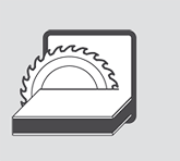
ALUCOBOND® PLUS can be cut with a vertical panel saw, circular saw, or jigsaw. Carbide tipped (CT) saw blades.
| Blade geometry | Tooth thickness approx. 2 – 4 mm, tapered to the inside to prevent jamming |
| Tooth geometry | Trapezoid tooth / flat tooth |
| Pitch t | 10 – 12 mm |
| Clearance angle α | 15° |
| Rake angle γ | 10° positive |
| Maximum feed s | 20 m/min |
Important: For ALUCOBOND® PLUS special carbide tipped (CT – quality K01) saw blades are used. The speed must be reduced by 50%.
Carbide tipped (CT) saw blades can be used for HOLZ-HER and Striebig circular panel saws. Trapezoid/flat tooth saw blade, flat teeth 45° chamfered can be used for burr-free edges.
| Saw blade-Ø | D = 300 mm (for Striebig vertical panel saw Standard II) |
| Number of teeth | t = 72 Speiser Code No. 070 60 651 |
| Saw blade-Ø | D = 250 mm (for Holz-Her vertical panel saw 1255 ALUCOBOND® PLUS) |
| Number of teeth | t = 60 Speiser Code No. 020 40 151 |
| Bore ø | D = 30 mm |
| Tooth thickness | 3.2 mm |
| Clearance angle α | 15° |
| Rake angle γ | 10 ° positive |
[/vc_column_text][/vc_tta_section][vc_tta_section title=”Punching” tab_id=”Punching”][vc_column_text]
ALUCOBOND® PLUS panels of any thickness can be punched using conventional sheet punching machines.
- For clean cuts, use sharp tools and dies with minimal cutting clearance (0.1 mm). Punching will cause a slight deflection at the cut edge of the impact side.
- Holes with a minimum diameter of 4mm can be punched.
- Distance between the adjacent hole edges should not be less than 4mm.
- Please ask for detailed information on how to perforate ALUCOBOND® PLUS before proceeding.
[/vc_column_text][/vc_tta_section][vc_tta_section title=”Contour Cutting” tab_id=”contour-cutting”][vc_column_text]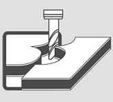
ALUCOBOND® PLUS can be cut to shape using a jigsaw, CNC machine and waterjet machine.
- While using a jigsaw, use saw blades that are used for cutting wood and plastic material.
- Cut abrasively while using a waterjet cutting machine. Pre-drilling of panels is required before commencing.
- While using a waterjet, a cut is needed in the middle of the panel as it is not possible to drill through using a waterjet.
- CNC machining centres should use a one-edged cutter.
[/vc_column_text][/vc_tta_section][vc_tta_section title=”Bending” tab_id=”Bending”][vc_column_text]
ALUCOBOND® PLUS can be bended using a bending press.
- The minimum required radius is r = 10 x t (t = panel thickness)
- The spring back effect of ALUCOBOND® PLUS is greater than that of a solid aluminium sheet.
- The die edges should be rounded and smooth.
- To prevent damage to the panel surface, protective foil must not be removed during bending.
- Additionally, the visible surface can be protected by using plastic pads of 1-2mm thickness
- Ideal die width: 2 x t + 2 x protective foil thickness + punch diameter + 15mm
- Before scaled-up production, testing on the sample panels is recommended.
Important: When bending ALUCOBOND® PLUS with an anodised surface, the bent area is brighter.

A = punch
B = protective foil
C = die
D = die width
r = radius[/vc_column_text][/vc_tta_section][vc_tta_section title=”Roll Bending” tab_id=”roll-bending”][vc_column_text]
 ALUCOBOND® PLUS can be bent using a roll bending machine (3 or 4 rollers). Make sure that the feeder does not exert too much pressure. Bending rollers which are also used for bending other metals must be thoroughly cleaned from swarf before processing ALUCOBOND® PLUS. Make sure to use only polished rollers free of dents and other defects. To prevent damage caused to the panel surface, the protective peel-off foil must not be removed during bending. Additionally, the visible surface can be protected by using plastic pads of 1-2mm thickness. Before scaled-up production, testing on the sample panels is recommended.
[/vc_column_text][/vc_tta_section][vc_tta_section title=”Routing & Folding” tab_id=”Routing-Folding”][vc_row_inner][vc_column_inner width=”5/6″][vc_column_text]
ALUCOBOND® PLUS composite panels can be shaped using a very simple processing method. The technique – called the routing and folding method – enables a fabricator to produce shapes of various kinds and sizes. A V-shaped or rectangular groove is routed on the reverse side of the ALUCOBOND® PLUS composite panel using a disk or end milling cutter. A thin layer of the core material should be left at the base of the groove, i.e. on the inside of the outer cover sheet. The untouched outer cover sheet can now be bent manually, giving an exact and clean folding line which follows the routed groove. The outer radius of the folded edge depends on the shape of the groove and its depth. We recommend that routing should be done using a vertical panel saw equipped with ALUCOBOND® PLUS grooving accessories, a CNC machining centre, a portable sheet milling machine, or a handheld router. The routing and folding method can be used for ALUCOBOND® PLUS composite panels with all available standard surface finishes.
Important: When folding ALUCOBOND® PLUS with an anodized surface, the folded edges are brighter.[/vc_column_text][/vc_column_inner][vc_column_inner width=”1/6″][vc_single_image image=”5658″ img_size=”full”][/vc_column_inner][vc_column_inner][vc_column_text]
Advantages
The convincing advantages of this unique technique are:
- Low investment cost
- Simple fabrication technique
- Folding can be done on site, saving transportation cost
- Low-cost fabrication of shaped components used in fascia and wall cladding, roof edgings, column cladding, flashings, etc.
- Flexibility in creating shapes
- Very economical
- Shapes are not limited by machine capacity
Benefits
- The fabrication of shaped components using ALUCOBOND®PLUS only requires a minimal investment outlay.
- Hand routers and sheet milling machines are inexpensive and can be used either in the workshop or on site.
- The fabrication of shapes in larger quantities is particularly economical using vertical panel saws equipped with ALUCOBOND®PLUS grooving accessories.

90° V-groove for folds up to 90°
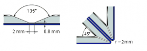
135° V-groove for folds up to 135°

Rectangular groove for folds up to 150°, depending on panel thickness. Not suitable for ALUCOBOND® A2.
[/vc_column_text][/vc_column_inner][/vc_row_inner][/vc_tta_section][vc_tta_section title=”Riveting” tab_id=”Riveting”][vc_column_text]
Riveting is possible using solid or blind rivets with conventional riveting tools. For exterior applications allow for thermal expansion and use a rivet attachment jig if necessary. ALUCOBOND® PLUS panels can be fastened together or joined to other materials using rivets commonly used in aluminium construction. For outdoor use and for use in areas of high humidity, make sure to use aluminium blind rivets with stainless steel mandrels to prevent unpleasant corrosive edges. When using aluminium blind rivets with steel mandrels, the mandrel should drop out after riveting (detachable version). Countersunk rivets are suitable for indoor use only.
For outdoor use please note:
- Use aluminium blind rivets that have been approved for construction with a 5mm shaft diameter and an attachment head diameter of 11mm or 14mm.
- Please take the thermal expansion of the panel into account (2.4 mm/m/100°C). To avoid jamming, the hole in the panel must be large enough to allow for expansion.
- With the shaft of the rivet fitting closely to the edge of the hole, the attachment head must cover 1mm of the area surrounding the hole.
- Multi-step drills or sleeves with corresponding diameters are used for centrically drilling holes into the panel and the substructure for centrically fitting the rivet.
- Rivet attachment jigs are used for fitting blind rivets without jamming, allowing for a tolerance of 0.3mm.
- Make sure to use rivet attachment jigs and rivets from the same manufacturer, as the height of the attachment head according to DIN 7337 may vary.
- The clamping thickness results from the thickness of the material to be riveted, plus an additional value of 2mm to ensure that the closing head is perfectly formed. In accordance with this clamping thickness the corresponding shaft length is determined in the tables provided by the rivet manufacturers. (L min = 14 mm).
Important:
During riveting many factors influence the exact tolerance of the rivets of 0.3mm (e.g. rivet head tolerance). We recommend testing on the fascia panels before commencing. Always remove the protective foil from the riveting surface area before riveting.
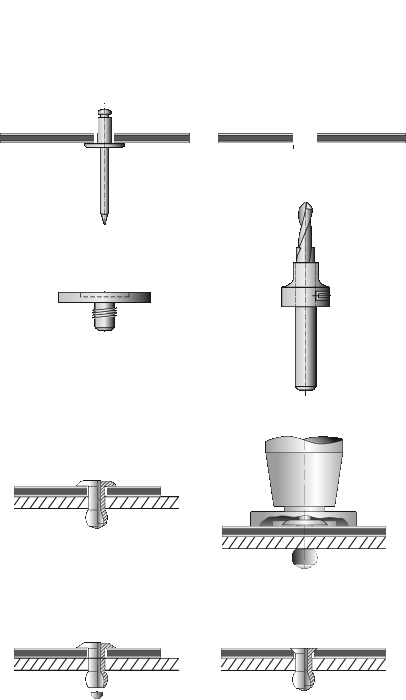 [/vc_column_text][/vc_tta_section][vc_tta_section title=”Screwing” tab_id=”Screwing”][vc_column_text]Threaded fasteners for outdoor use
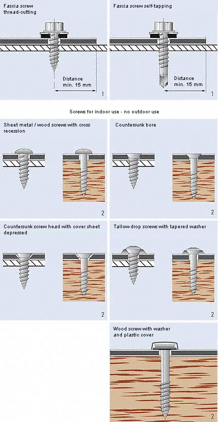
For outdoor use make sure to take the thermal expansion of the panel into account. To avoid jamming, the hole diameter in the panel must allow for the expansion. Fastening without jamming is possible using fascia screws made of stainless steel with sealing washer (Fig. 1) that have been approved for construction. The screws must be suitable for the corresponding substructure (please note the information given by the manufacturer). The screws should be tightened with a torque wrench or screwdriver so that the sealing washer is placed on the panel for sealing the bore hole without exerting pressure to the panel. Multi-step drills or sleeves with corresponding diameters are used for centrically drilling holes into the panel and the substructure, and for centrically fitting the rivet. Important: Make sure to remove the protective foil only from the screwing area prior to screwing.
Threaded fasteners for indoor use
Screws for sheet metal and wood with different head shapes can be used for indoor application (Fig. 2). They do not normally allow for any panel expansion. Countersunk screws can be inserted by the usual countersinking method or by depressing the aluminium surface into the panel. When depressing the aluminium surface, the hole diameter in the panel must be larger than the screw diameter.
 [/vc_column_text][/vc_tta_section][/vc_tta_accordion][/edgtf_accordion_tab][edgtf_accordion_tab title=”Fixing Systems”][vc_row_inner][vc_column_inner width=”1/3″ css=”.vc_custom_1712212928306{padding-bottom: 40px !important;}”][vc_single_image image=”6359″ onclick=”link_image”][vc_column_text css=”.vc_custom_1704878121148{padding-top: 10px !important;}”]Tray panels suspended
on stainless steel bolts / vertical panel layout[/vc_column_text][/vc_column_inner][vc_column_inner width=”1/3″ css=”.vc_custom_1712212936353{padding-bottom: 40px !important;}”][vc_single_image image=”6361″ onclick=”link_image”][vc_column_text css=”.vc_custom_1712212157738{padding-top: 10px !important;}”]Tray panel screwed
for vertical panel layout[/vc_column_text][/vc_column_inner][vc_column_inner width=”1/3″ css=”.vc_custom_1712212943538{padding-bottom: 40px !important;}”][vc_single_image image=”6362″ onclick=”link_image”][vc_column_text css=”.vc_custom_1712212185540{padding-top: 10px !important;}”]Tray panels SZ-20
tongue and groove design / horizontal panel layout[/vc_column_text][/vc_column_inner][/vc_row_inner][vc_row_inner][vc_column_inner width=”1/3″ css=”.vc_custom_1712212957169{padding-bottom: 40px !important;}”][vc_single_image image=”6363″ onclick=”link_image”][vc_column_text css=”.vc_custom_1712212218355{padding-top: 10px !important;}”]Glued
for vertical / horizontal panel layout[/vc_column_text][/vc_column_inner][vc_column_inner width=”1/3″ css=”.vc_custom_1712212963361{padding-bottom: 40px !important;}”][vc_single_image image=”6364″ onclick=”link_image”][vc_column_text css=”.vc_custom_1712212213572{padding-top: 10px !important;}”]Riveted / screwed
on omega carrier section for vertical panel layout[/vc_column_text][/vc_column_inner][vc_column_inner width=”1/3″ css=”.vc_custom_1712212968809{padding-bottom: 40px !important;}”][vc_single_image image=”6365″ onclick=”link_image”][vc_column_text css=”.vc_custom_1712212199323{padding-top: 10px !important;}”]Riveted / screwed
on vertical profiles for vertical panel layout[/vc_column_text][/vc_column_inner][/vc_row_inner][vc_row_inner][vc_column_inner width=”1/3″ css=”.vc_custom_1712212981585{padding-bottom: 40px !important;}”][vc_single_image image=”6367″ onclick=”link_image”][vc_column_text css=”.vc_custom_1712212224203{padding-top: 10px !important;}”]Clamped / screwed
double “top-hat”sections[/vc_column_text][/vc_column_inner][vc_column_inner width=”1/3″ css=”.vc_custom_1712212986681{padding-bottom: 40px !important;}”][vc_single_image image=”6364″ onclick=”link_image”][vc_column_text css=”.vc_custom_1712212229299{padding-top: 10px !important;}”]Riveted weather boarding
on aluminium substructure[/vc_column_text][/vc_column_inner][/vc_row_inner][/edgtf_accordion_tab][edgtf_accordion_tab title=”Fire Classification”][vc_column_text]
| Country | Test accord. to … | Classification |
|---|---|---|
| Australia | AS ISO 9705
AS 1530.3 Indices
EN 13501-1 |
Group 1 material
SMOGR A 1.385 m2 / s2 0 (ignitibility) 0 (flame spread) 0 (heat evolved) 0-1 (smoke development) B-s1, d0 |
| China | GB 8624-2012 | Class B1 (B- s1,d0, t0) |
| EU | EN 13501-1 | Class B-s1, d0 |
| Germany | EN 1187 (method 1) / DIN 4102-7 |
passed |
| Great Britain
England / Wales / Scotland |
BS 476, Part 6 & 7
BR 135 BS 8414 part 1 & 2 |
Class 0
met the performance criteria Passed |
| Malaysia | BS 8414-1
BS 476, Part 6 BS 476, Part 7 Approved for outdoor wall cladding of any type of building without height limit |
Passed
Class 0 Class 1 |
| Poland | PN-90/B-02867 | NRO |
| Russia | GOST 30244-94
GOST 30402-95 GOST 12.1.044-89 GOST 12.1.044-89 |
G1 (combustibility)
W1 (flammability) D1 (smoke development) T1 (toxicity) |
| Singapore | EN 13501-1
BS 476, Part 6&7 NFPA 285 Approved for outdoor wall cladding of any type of building without height limit |
Class B-s1, d0
Passed Passed |
| Switzerland | VKF | RF2 |
| UAE | NFPA 285 EN 13501-1 ASTM E84 |
Passed Class B-s1, d0 Class A |
| USA | ASTM E84 NFPA 285 |
Class A Passed |
[/vc_column_text][/edgtf_accordion_tab][edgtf_accordion_tab title=”Installation | Maintenance | Storage | Handling Guideline”][vc_row_inner][vc_column_inner width=”1/2″][vc_single_image image=”5681″ img_size=”medium” onclick=”link_image” css=”.vc_custom_1712145308973{padding-top: 10px !important;padding-bottom: 10px !important;}”][/vc_column_inner][vc_column_inner width=”1/2″][vc_single_image image=”5682″ img_size=”medium” onclick=”link_image” css=”.vc_custom_1712145272635{padding-top: 10px !important;padding-bottom: 10px !important;}”][/vc_column_inner][/vc_row_inner][vc_column_text css=”.vc_custom_1713270480146{padding-top: 10px !important;}”]To avoid possible reflection differences (for metallic, special effect, naturAL, and spectra colours), it is recommended to install the panels in the same direction as marked on the protective peel-off-foil. Colour variations may occur between panels originating from different production batches. To ensure colour consistency, the total requirement for a project should be placed in one order.
| Dimensional tolerances | ||
|---|---|---|
| Thickness | ±0.2 mm | |
| Width | -0 / +4 mm | |
| Lengths | 1000 – 4000 mm | -0 / +6 mm |
| Lengths | 4001 – 8000 mm | -0 / +10 mm |
Due to the production process, a displacement of the cover sheets of max. 2 mm to one side may occur along the longer sides of the panels if not specially trimmed.
Protective foil
- To avoid residuals of glue sticking to the surface of the panels due to UV radiation, it is recommended to remove the protective foil as soon as possible after the installation.
- The protective foils and the panel surfaces must not be marked using ink (marker), adhesive tapes or stickers, as the lacquered surfaces could be damaged by solvents or plasticizers.
- Make sure to remove the protective foil as soon as possible after installation as weathering for a longer period could make the foil difficult to remove.
Cleaning and maintenance
The frequency of cleaning depends on the design and the degree of soiling. For further information, please refer to our brochure.
[/vc_column_text][vc_row_inner content_placement=”bottom”][vc_column_inner width=”1/12″][vc_single_image image=”7682″ img_size=”full”][/vc_column_inner][vc_column_inner width=”11/12″][vc_column_text]
ALUCOBOND®
Download our Alucobond processing manual
![]() PDF [4.23 MB].[/vc_column_text][/vc_column_inner][/vc_row_inner][vc_column_text]
PDF [4.23 MB].[/vc_column_text][/vc_column_inner][/vc_row_inner][vc_column_text]
Storage / Handling
- Protect ALUCOBOND® PLUS pallets during storage against rain, penetration of moisture and condensation.
- Only pallets of identical size should be stacked, with a maximum of 6 pallets stacked on top of each other.
- Storage exceeding 6 months should be avoided, as it may become difficult to remove the protective foil.
- When stacking the panels nothing should be placed in between them, as this could produce marks on the panels.
Recycling
ALUCOBOND® PLUS can be fully recycled, i.e. both the core material and the aluminium cover sheets can be recycled and used for the production of new material.[/vc_column_text][/edgtf_accordion_tab][/edgtf_accordion][/vc_column][vc_column][/vc_column][/vc_row]